
This site evolved from a need to know how things work, and in this case wanted to learn and understand the wordpress.com interface. At the same time, will use this learning opportunity to create a quick reference guide to document my Arduino / ATtiny based micro controllers Wireless Weather Station, Anemometer, Wind vane, Temperature, Rain gauge / (Ham Radio) Band Decoder, Automatic CW IDer experiments.
Please Note: This site contains mixed content:
Firefox 14+ automatically redirect http sites to https without warning. This causes a problems on sites with mixed content. Some features on this site like the weather Station widget in the right hand column won’t display unless Mixed Content is enabled. To display mixed content in Firefox read this, to Disable Mixed Content in Firefox read this.
Experiments:
ATtiny
Arduino
Ham Radio
-
- Ham Radio Automatic CW IDer ATtiny / Arduino Based
- Ham Radio Tiny IBM PS2 Keyboard CW Keyer Interface ATtiny Based
- Ham Radio ICOM Yaesu Band Decoder Arduino / ATtiny Based
- Ham Radio Brownout – Blackout AC Power Automatic Disconnect
- Ham Radio ICOM CI-V / RS232 to TTL Level Converter
- Ham Radio ICOM IC756 PRO – II – III / PS125 Fan Modifications
- Ham Radio Center Feed Tee Connector For Dipole Antennas
- Ham Radio 20 /40 Meter Short Coil Loaded Dipole Antenna
- Ham Radio 20 /40 Meter Short Coax Trap Dipole Antenna
- Ham Radio 40 /20 /15 Meter Half Wave Fan Dipole Antenna
- Ham Radio 2.5:1 Balun for Skywire Loop Antenna
- Ham Radio 1:64 Matching Network (Balun) for End-Fed Antenna
- Ham Radio miniVNA PRO Installation / User Notes
Ham Radio Remote
-
- Simple Ham Radio Remote
- Ham Radio Remote Why operate your Ham Station Remotely
- Ham Radio Remote via WebRTC Audio / Raspberry Pi
- Ham Radio Remote Control via Yaesu PCC / Raspberry Pi
- Ham Radio Remote Base Web Audio API / Node.js Server
- Ham Radio Remote Base HTML5 Audio / Node.js Server
- Ham Radio Internet Remote Base Via A Raspberry Pi
- Ham Radio Remote Base A Complete Solution
- Ham Radio Remote Base Audio Interface
LDMOS Solid State Amplifier (SSPA)
Raspberry Pi
-
- Raspberry Pi Ham Radio Powering a Pi from a 13.8 volt DC Power Supply
- Raspberry Pi Ham Radio Remote Control via Yaesu PCC / Raspberry Pi
- Raspberry Pi Ham Radio Remote Base Web Audio API / Node.js Server
- Raspberry Pi Ham Radio Remote Base HTML5 Audio / Node.js Server
- Raspberry Pi Ham Radio Internet Remote Base Via A Raspberry Pi
- Raspberry Pi Ham Radio Remote Base A Complete Solution
- Raspberry Pi Stream Live Ham Radio/Police Scanner Audio
- Raspberry Pi Ham Radio AA6E Tiny Python Panadapter
- Raspberry Pi Bind9 DNS/DDNS (Dynamic DNS) Server
- Raspberry Pi / ATtiny 433Mhz Weather Station RF Communication
- Raspberry Pi Install Nginx, PHP, MySQL and uWSGI for Python cgi
- Raspberry Pi Image Too Big For Same Size SD Card
- Raspberry Pi Stretch Setting Up WiFi Access Point / Hotspot
- Raspberry Pi 4 Screen Blanking then Entering Power Save Mode
Cable Modem Routers
-
- NETGEAR R7000 Router Bridged with Comcast Xfinity ARRIS TG1682G Gateway
- NETGEAR C6900 Cable Modem Router Activate with Comcast Xfinity
- NETGEAR No-IP Setup Free Dynamic DNS on Cable Modem Routers
Misc.
Completed Experiments:
Experiments Progress:
Raspberry Pi / ATtiny 433Mhz Weather Station RF Communication – (Completed)
Raspberry Pi Stream Live Ham Radio/Police Scanner Audio – (Completed)
Raspberry Pi Ham Radio Internet Remote Base Server/Client – (Completed
Ham Radio Automatic CW IDer ATtiny/Arduino Based – (Completed)
Ham Radio ICOM CIV to Yaesu BCD Band Decoder ATtiny/Arduino Based – (Completed)
ATtiny/Arduino Wireless Weather Station ATtiny/Arduino Based – (Completed)
Raspberry Pi 433Mhz RF Communication Via ATtiny
Exploring the feasibility to use an ATtiny to convert 433Mhz weather station data stream to serial data for the Raspberry Pi. Click here
Raspberry Pi Stream Live Ham Radio/Police Scanner Audio
Exploring the feasibility of streaming live Ham Radio, Police Scanner, Microphone Audio from a Raspberry Pi Streaming Audio Server. Click here
Raspberry Pi Ham Radio Internet Remote Base Server/Client
Exploring the feasibility of using a pair of Raspberry Pi with some open source free-ware as a Ham Radio Internet Remote Base Server/Client for Icom, Yaesu, Kenwood Ham Radio Transceivers. Click here
Ham Radio Automatic CW IDer ATtiny/Arduino
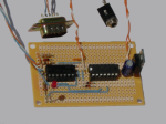
NOV 8, 2014: Built Ham Radio Automatic CW IDer ATtiny / Arduino Based around a Amtel ATtiny85. Have been working on the sketch off and on, have tested the circuit on a prototype breadboard. Now just need to finish it up testing on the air.
NOV 15, 2014: Have been testing the HF Automatic CW Keyer / IDer / ID Reminder prototype on thea IC756 PROIII and all is working as expected.

NOV 16, 2014: Posted another schematic showing how the ATtiny85 HF Automatic CW Keyer / IDer / ID Reminder can be configured. The Rev4 schematic shows the additional command buttons, Send station identification, Amp Tuning Aid, station identification On/Off, Fan On/Off and transceiver PTT. Currently testing the Rev4 prototype on the IC756 PROIII transceiver. The 13.8vDC Power, Mic In, PTT and GND provided via the Accessory (1)one Din plug on the back of the transceiver. To activate the ID timer just press the mic button, the ID LED will start pulsing when the ID timer is active, after a 9 minutes count down the ID LED will remain ON, indicating that it’s time to identify the station. The ID Reminder will automatically identify the station and reset the ID timer when you are talking on the radio. If you are listing to the radio the ID Reminder will wait until the next time mic button is pressed to identify the station then reset the ID timer. If the mic button is not pressed within a 5 minutes window after the ID LED stops pulsing, the ID timer will automatically turn the ID LED Off and reset the ID timer ready for the next QSO.
NOV 22, 2014: Rev4 prototype testing is going really well, CW audio sounds really good on SSB, adjusted the audio level for a low background station identification. Posted a schematic for a Tiny battery powered ID Reminder / Timer. Still working on the sketch see the Ham Radio Automatic CW IDer Arduino / ATtiny page.
NOV 26, 2014: A slightly related distraction: Ham Radio Tiny IBM PS2 Keyboard CW Keyer Interface ATtiny Based. Brought out the Elecraft KX3 and got interested in the built in PSK option. Looking through the KX3 user manual (Data Modes) read that the KX3 supports data operation via a computer and special software. So launched the K3 & KX3 programing reference manual and found the (KY) command will send Keyboard DATA through the RS232 port, but there is a 24 character limit. Back to the KX3 user manual read that the KX3 can convert CW form the CW KEY jack or the KXPD3 paddle to FSK D & PSK D Data. Since the KX3 can decode CW, PSK31 (PSK D) and RTTY (FSK D) on the display. Decided to build a ATtiny based Tiny IBM PS2 Keyboard CW Keyer Interface.
DEC 12, 2014: Have been working on the PS2 CW Keyer sketch all working great on Arduino UNO, but include so many great option that it ran out of ram when ported to Attiny85. So will have to remove some option on the ATtiny85 version.
Ham Radio Icom CIV To Yaesu BCD Band Decoder ATtiny/Arduino
OCT 26, 2014: Ham Radio ICOM Yaesu Band Decoder Arduino / ATtiny Based. The sketch will be developed on a Arduino UNO then ported to a ATtiny84 for the final prototype. Ordered the ATtiny84, should arrive in a couple of day’s. Still have to draw the schematic and ATtiny84 pin-out graphics.
OCT 27, 2014: Updated webpage, posted schematic and ATtiny84 pin-out graphics.
NOV 1, 2014: Created the ICOM CI-V to Yaesu BCD band data sketch, tested sketch on Arduino UNO and ATtin84 works as expected. Updated ATtiny84 pin-out graphics and ICOM CI-V to Yaesu band decoder schematic. Schematic updates: added a heartbeat LED to monitor TX/RX data to and from the transceiver. The heartbeat LED blinks every second to request the current frequency when transceiver is idle and ON, and it will flash rapidly when the frequency dial is turned. BCD band data will only update when the band has changed, it will not update BCD band data if frequency is within the band limits. BCD data will go to b1111 when frequency goes out of band.
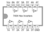
NOV 2, 2014: Have been testing ICOM CI-V to Yaesu band decoder on a breadboard and all is working well, but now looking for a way to eliminate the transistor based CI-V / RS232 level converters. Ordered a MAX232 IC. Scanning the MAX232 data sheet, noticed that the MAX232 used four internal inverters to convert RS232 level to TTL / TTL to RS232. So why not use a cheap hex inverter IC to accomplish the same thing. Searching the internet found the following websites My Weblog and VE1ZAC which used a hex inverter IC to convert RS232 to TTL. So with that information, create a new ICOM CI-V to TTL / RS232 to TTL level converter which used a single hex inverter IC. Replaced the transistor RS232 to TTL level converter with the RS232 7404 hex inverter level converter, and all is working well.
Note: There is nothing wrong with the transistor level converter, it also work well.
NOV 4, 2014: Last night wire up the ICOM CI-V to Yaesu band decoder on a prototype board. All is working as expected. The RS232 7404 hex inverter level converter allows the band decoder to either be connect through an external CI-V to RS232 level converter or directly to the ICOM remote CI-V port, which then eliminates the external CI-V to RS232 level converter. On the prototype board, only wired in the heartbeat LED to indicate that the band decoder is polling the radio.

This is a very inexpensive Ham Radio Band Decoder (with a custom sketch) it can convert frequency data form most CAT port to BCD band data. That band data can then be used to auto band switch some amplifiers, or with an additional BCD to decimal decoder and some relays switch in antennas, band filters by band.
NOV 7, 2014: Posted a schematic for the ICOM CI-V / RS232 to TTL 7404 hex inverter level converter Here.
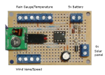
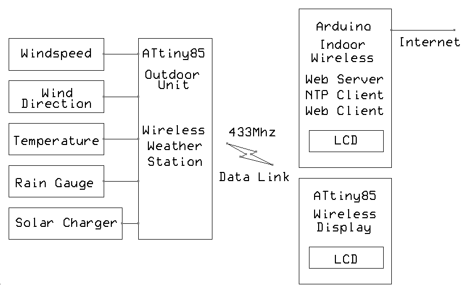
ATtiny/Arduino Wireless Weather Station
Jan 31, 2014: Installed the complete prototype ATtiny remote wireless weather station outside on a mast, hopping for a nice clear sunny day the tomorrow, to test the solar charger. Well guess what it’s raining today, as of this post the remote weather station has been online for eighteen(18) hours on the 5v battery pack. Need at least eighth(8) hours off sun to recharge the batteries, now just waiting to see when the station shuts down. The ATtiny BOD (Brown-out detection) set to 4.3v that’s when the micro will power down. All function are working well, Local Weather widget, Google Charts api weather Trend graphs are all updating. Only annoying problem is the range between the 433Mhz TX/RX modules. Possibly need to build a couple of high-gain antennas, right now the antenna is just a 6″ piece of wire, not the best antenna for very low powered 433Mhz TX/RX modules.

Feb 3, 2014: The wireless weather station running on the 5v battery pack for thirty-two(32) hours. Measure the battery voltage down to 3.9v, waiting for the sun to hit the solar panel to recharge the battery. The sun hit the solar panel at 8:45am, Solar panel output was 8.25v, no load. Replaced the 10 ohm current limiting resistor with a 1 ohm to up the charging current from 50ma to 150ma still in the save charging range. Will check battery voltage again this evening after sun goes down. All is working well but need to move temperature sensor out of the control box to get accurate temperature reading, but for now it will show how hot the controller gets inside the box. Measured the battery voltage this evening 5.6v, solar charge time about 9 hours, looks like it took a good charge. Will again measure battery voltage in the morning.
Feb 5, 2014: Slight set-back the solar charger is not fully charging the battery pack, so back to the drawing board. Found a good solar charger Tutorial By Phillip Stearns followed the tutorial made all the measurements and found out that it would take about sixth-nine(69) hours to fully charge the 5v battery pack. Now working on a better solar charger solution, everything else is working as expected…
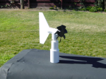
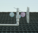
Feb 18, 2014: Still waiting for ordered part to arrive. Reset the ATtiny85 BOD fuse to 2.7 volts. Did that to use 3.6v battery pack with a 4.5 v 1.5w solar cell, hopefully that will keep the battery charged. While waiting for part to arrive, decided to build a three(3) Cup Anemometer/Wind Vane. Now is a good time to build a Cup Anemometer since the stores are stocking a good assortment of plastic Easter eggs for Easter.
Feb 19, 2014: Found at Jameco Electronics 7/8 diameter 10K no stop precision potentiometer, Digi-Key also has 7/8 diameter 10k no stop precision potentiometer and they have 7/8 diameter 20k no stop precision potentiometer. Great for making Wind Vane’s. The ATtiny Wireless Weather Station uses a no stop 7/8 diameter 10k precision potentiometer to sense the wind direction.
Feb 21, 2014: Finished the Arduino/ATtiny weather station 3 Cup Anemometer-Wind Vane, now have two different style anemometer/wind direction sensor which can be used with the ATtiny & Arduino wireless weather station / web server. Next will build a Temperature sensor solar radiation shield.
Feb 22, 2014: Updated the solar charger circuit (found simple solar circuit here) included a 7805 voltage regulator ahead of this circuit, to use a 6 to 12v solar panel. Still not limiting the charging current giving the battery as much current as the solar panel has available. Re-installed the ATtiny weather station at 9:00am with a 3.6v 300ma Nicad battery pack no-load voltage 4.14v. Still having distance problems between 433Mhz TX/RX modules, but discovered that wrapping some aluminum foil over the top 1″ of the TX/RX antenna improved the distance between the 433Mhz TX/RX modules.
Feb 23, 2014: Measured the battery voltage this morning 7:00am 3.80v no-load still above the 3.6v battery pack voltage. Sun came out at 10:00am battery should be re-charging, will measure battery voltage this afternoon after dark. Measured battery voltage at 6:19pm 8hr charge, battery voltage under load 3.97v. Will take another battery voltage measurement under load tomorrow morning.
Feb 24, 2014: Measured battery voltage at 7:10am 3.60v under load. Battery lost 0.37v over 8hr period. Well reworked the solar charger circuit again, removed the 7805 regulator (read on the internet that it just wasted a lot of power), replaced the 6v 1.5w solar panel (8.12v in full sun light no-load), with a 4.5v 1.5w solar panel (5.5v 334ma in full sunlight no-load) and used a 3.6v 830ma Nicad battery pack. Measured the charging current in full sunlight to the battery under load 83ma. Weather station back online at 10:30am battery voltage under load 4.14v, after sunset 5:49pm measured battery voltage under load 4.12v so it ran on solar power for 6hr.
Date 	Time 	Volt  Drop  Hr    Sun-up  Time    Volt  Charge Hr
2/24/14 10:30am 4.14v 0.00v 00    10:30am 05:49pm 4.12v -0.02  06
2/25/14 06:35am 3.75v 0.37v 12    09:30am 07:19pm 3.96v +0.21  10
Feb 27, 2014: The Solar charger testing has been a little slow with the rainy weather, but another solar charger circuit update, hopefully the last one. Installed a LM1117 3.3v LDO voltage regulator after the solar charger’s diode switching network. Went back to the 6v 1.5w solar panel and replaced the 3.6v Ni-cad 830mAh battery pack with a 5v Ni-mh 1800mAh battery pack. Had a little sun this morning, so made some solar charger current measurement in full sun light, 6v output with 33mA load 225mA charge going into the battery, that’s good since C/10 charge equals 180ma. Now testing to see how long the weather station will run on the 5v Ni-mh 1800mAh battery pack, should run for 2.5 days. So far 24hr with very little voltage drop 5.38v to 5.05v -.33v drop, was able to solar charge the battery for 1hr in cloudy sky’s battery voltage back to 5.28v. This is much better then the previous solar charger circuit update. Currently the Wireless Weather Station is consumes a study 33ma. The sun came out, so re-installed the weather station will just monitor the up time.
Feb 28, 2014: Needed to know exactly where that 33mA was going, so made a lot of voltage and current measurements today.
| ATtiny85 Power Consumption | |
| ——————————- | 1Mhz BOD disabled |
| 5.5v | 2.67mA |
| 3.3v | 1.05mA |
| ——————————- | 8Mhz BOD disabled |
| 5.5v | 8.94mA |
| 3.3v | 4.20mA |
| ——————————- | 8Mhz BOD disabled – Programed |
| 5.5v | 9.00mA |
| 3.3v | 4.44mA |
| LM1117 | Quiescent Current |
| 5.5v | 5.78mA |
After making the above current measurement, installed the new programed ATtiny85 on the prototype board and measured the current.
| ATtiny85 Wireless Weather Station Power Consumption | |
| ——————————- | 8Mhz BOD disabled – Programmed |
| 3.3v | 4.44mA |
| ——————————- | LM1117 |
| 5.5v | 5.78mA |
| Total Current with TX | 10.29 – 12.00 mA |
Now that’s much better. Discovered that the ATtiny85 used on the prototype for testing must be shorted internally, even though it still works without any problems, it just suck-up a study 26mA of current by itself. The new ATtiny85 only take 4.44mA and the LM1117 take another 5.78mA as per data sheet. The Wireless Weather Station back online 11:00am with fully charged battery pack 5.59v 1800mAh Ni-mh. So estimated battery live 1800mAh/12mA=150h/24h=6.25 days.
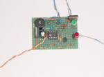
Mar 04, 2014: On battery power for four(4) day’s all is working well. Broken overcast sky today just enough sun to lightly charge the battery pack. Currently working on ATtiny85 Wireless Weather Station Remote Serial LCD Display which is up and running now for one(1) day on breadboard without any problems.
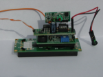
Mar 05, 2014: Built the prototype ATtiny85 Wireless Weather Station Remote Serial LCD Display made it small enough to piggy-backed on the back of the Parallax Serial LCD display. Board size 2×3/4 inch the component count is so low that there is plenty of space.
Mar 05, 2014: The Arduino & ATtiny Weather Station on Solar/Battery power for eight(8) days now with out any problems. Solar charger working as expected, Anemometer & Wind vane & Temperature & Rain gauge sensors all working without any problems. The Arduino Wireless Weather Station & Web Server & Internet Client & NTP Client all working without any problems. The ATtiny serial remote LCD display also working without any problems. Thing are looking good with the Arduino / ATtiny weather station. So while the prototype Weather Station is run, will work on the Ham Radio ATtiny/Arduino Based Automatic Call sign CW IDer.
Mar 12, 2014: The Arduino & ATtiny Weather Station on Solar/Battery power for twelve (12) days now with out any problems. Solar charger is working great, measured the battery voltage this morning 5.28v. Made some software updates this morning, now sending Vcc chip voltage, which is read from a fixed reference voltage inside the ATtiny85 chip, also sending raw ADC LM35 Temperature data, which is then converted to Celsius/Fahrenheit in the Arduino Wireless Weather Station & Web Server. Knowing the Vcc voltage, is important to Auto-calibrating the LM35 Temperature sensor. Really need to remove the LM35 temperature sensor from the controller housing, to get accurate Outside Temperature readings, but having hard time finding the parts needed to build the Temperature Solar Radiation Shield.
Mar 13, 2014: A lot of updates today Software and Hardware. Hardware reworked the Wind vane circuit installed a Vane CAL potentiometer to calibrate the wind vane.
Software changes:
- Weather Station sensor now has their own ID so the Arduino Wireless Weather Station & Web Server can receive weather data form multiple ATtiny wireless weather stations / wireless weather sensors.
- Wind vane calculation removed from the ATtiny85 wireless weather station, and moved to the Arduino Wireless Weather Station & Web Server.
- Temperature calculation removed from the ATtiny85 wireless weather station, and moved to Arduino Wireless Weather Station & Web Server.
- Updated Temperature Auto-Calibrate subroutine.
Item 2 & 3 makes weather sensor formula testing a lot easier.
Mar 15, 2014: Finally found the parts needed to Built the Arduino/ATtiny weather station Temperature sensor Solar Radiation Shield.
Mar 18, 2014: Eighteen(18) day’s on solar / battery power without any problems, measured battery voltage a couple of time in the morning, always fully charged 5.25v to 5.28v. Have been tweaking the LM35 temperature sensor, now within 0ne(1) to two(2) degree of the reference digital thermometer, but even though the temperature sensor solar radiation shield has been build, still have not removed the LM35 temperature sensor out of the wireless weather station control box. On Feb 22, 2014 mentioned a possible solution for the TX/RX distance issue, by warping some aluminum foil wrap over the top 1″ of the 433Mhz TX/RX antenna. The aluminum foil is basically capacity coupled to the end of the 433Mhz TX/RX antenna (not connected to the wire). Installed inside the wireless weather station control box, the aluminum foil just covers the ATtiny85 weather station board and the top 1″ of the antenna is inserted into the aluminum foil, have had no 433Mhz TX/RX module distance issues since. Probably not the best solution but it solved the distance issue.

Mar 19, 2014: Installed a solar radiation shield over the ATtiny85 wireless weather station control box. This will keep the temperature down inside the control box. A lot of progress made since the prototype weather station was first installed on the mast back on Jan 31, 2014. It’s now a real working weather station sending weather data to the internet Local Weather widget and Google Charts api weather Trend graphs…

Mar 22, 2014: Moved the LM35 temperature sensor into temperature solar radiation shield and aligned Van anemometer North.
Mar 23, 2014: The temperature solar radiation shield working great, now getting stable accurate outside temperature readings.
Mar 25, 2014: Organized web pages and created another Local Weather widget to display Arduino / ATtiny wireless weather station data.
Apr 2, 2014: Arduino / ATtiny weather station and Solar battery charger up and running for thirty(30) days without any problems everything working perfect.
Apr 12, 2014: Machined a counter weight out off a 1/2″ steel bolt for the three(3) cup anemometer, wind vane (as you might have noticed, the counter weight was missing in all the previous three(3) Cup Anemometer, Wind vane photos). Been researching how to use the wire.h library with 433Mhz RF communication. Did use the wire.h library to intercept/decode the Oregon Scientific wireless THGR266 Thermo-Hygro sensor. But still not sure how to use the wire.h library to transmit sensor data.

Apr 14, 2014: Ordered more sensors: DHT11 Humidity / Temperature sensor, BMP180 barometer sensor and HMC5883L triple axis compass sensor. Will build another complete Arduino Wireless Weather Station Web Server Data Logger around a Mega 2560 will add BMP180 barometer sensor (using the Arduino Mega 2560 for additional programing space). ATtiny Wireless Weather Station Remote Outdoor Unit will replace the LM35 temperature sensor with an DHT11 Humidity / Temperature sensor. Need to add Humidity TX/RX to the software.
Apr 20, 2014: Built another 3 Cup anemometer, wind vane with more readily available small 1 5/8″ diameter plastic Easter eggs. Used only one(1) 1/8″ by 12″ aluminum rod for the wind vane, cut 3″ off for the front had 9″ left for the tail. The tail fin is 7 3/8″ high, 3″ wide in the center, the center is 3 1/2″ from the top, the top/bottom are 2 3/8″ wide, a 3″ slot was cut down the center of the tail rod to hold the tail fin. The counter weight about 1 1/8oz.

May 5, 2014: Arduino /ATtiny Wireless Weather Station now up and running without any problems on solar power for two(2) months. Today replaced the Van Anemometer with the small three cup anemometer / wind vane in the photo above, also replaced the LM35 temperature sensor with an DHT11 humidity / temperature sensor, updated all the necessary software and reinstalled the station. All is working well.
May 6, 2014: Updated graphic weather widget, added dew point and rain. Need to find a way to dampen the weather vane, it’s way to sensitive. Updated ATtiny Wireless Weather Station Remote Outdoor Unit schematics.
May 7, 2014: Was able to dampen the weather vane using four(4) foam washers placed around the potentiometer shaft, between the wind vane and the potentiometer body. Wind vane now move smoothly in gusty winds. Working on the filtering out DHT11 reading errors.
May 9, 2014:  Created a windows system tray app to easily view the weather station widget on the desktop. To launch the weather station widget left mouse click the local weather icon in the system tray, to hide weather station widget right mouse click weather widget.
Was able to filter out the DHT11 reading errors. All is working well no other problem discovered since the last conversation from the LM35 temperature sensor to the DHT11 humidity / temperature sensor.
May 18, 2014: Added the following to the Weather Widget Wind Chill, Heat Index and Temperature Humidity Wind (THW) Index. Heat Index will only display at temperature above 70° F and Wind Chill will only display below 50° F. Will not add the barometer sensor.
May 26, 2014: Searching today for a smaller Solar Panel for a second Wireless Weather Station Remote Outdoor Unit, found at Harbor Freight a Solar Powered Fountain Pump Item #66093 with a 7v 1.2w solar panel dimensions 4.5″ x 4.5″ perfect size. The Solar Powered Fountain Pump was on sale. I had a 25% off super coupon and a free 7 function digital multimeter super coupon. So the 7v 1.2w solar panel with the free 7 function digital multimeter would only cost $12.00. But can the 7v 1.2w solar panel charge a 5v 2100 mAh NiMh battery pack?.

So I bought a Solar Powered Fountain Pump at Harbor Freight, just to make the somel voltage measurements.
Solar Panel Only Test
Resistor      Voltage    Current(Amps)    Power(Watts)
Open          7.72       0.24             1.85
268           7.60       0.03             0.22
120           7.42       0.07             0.51

Solar Panel With Charger circuit no battery pack connected
Open          7.70       0.24             1.84
268           7.37       0.03             0.22
120           7.21       0.07             0.50

Solar Panel With Charger circuit with battery pack connected
Open          6.06       2.83            17.14
268           5.83       0.03             0.17
120           5.78       0.05             0.28

Solar Panel With Charger circuit Charging 5v Battery Pack
Load          Voltage    Load Current     Charge Current
Open          6.21
268           5.98       0.03             0.16
120           5.91       0.05             0.13
From the measurements above the Solar Powered Fountain Pump Solar Penal can keep a 5v 1200mAh NiMh battery pack charged.
May 28, 2014: Second ATtiny Wireless Weather Station Remote Outdoor Unit built station ID2. Solar Powered Fountain Pump Solar Panel working just fine will charge battery pack and run the stationID2 when the suns out. Both station are currently up and running station ID1 on the internet station ID2 on an ATtiny Wireless Weather Station Remote Serial LCD Display. Measured charging current at noon in full sunlight 180mA. A very low 5v 2100mAh NiMh battery pack should take fourteen(14) hours to fully charge. So a fully charged battery pack charging eight(8) to ten(10) hours daily at 180mA should keep the battery topped off. Will see…
May 30, 2014: look like we have a keeper, measured battery voltage this morning 5.40v the Solar Powered Fountain Pump Solar Panel is keeping the battery charged. The Second ATtiny Wireless Weather Station Remote Outdoor Unit is working perfect.
Jul 06, 2014: The Arduino / ATtiny wireless weather station up and running for five(5) months without any issues.
ATtiny sketch developed on an Arduino UNO then shrunk and optimized for the ATtiny!
This site is currently under construction… Best viewed in FireFox
Note: The WordPress.com learning experience has gone really well, after figuring out how to create the front-page. Found the Dashboard very easy to use, and now understand the process. A Free Blog @ WordPress.com is a good thing.
