The Experiment: ATtiny Based Wireless Weather Station. Build a 433Mhz wireless weather station remote outdoor unit around an Atmel ATtiny85 micro-controller, with the following sensors, Anemometer, Wind vane, Temperature, Rain gauge plus Solar battery charger.
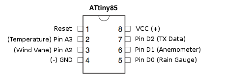
The challenge, the ATtiny85 only has 8-pins, 8KB ISP flash memory and pin1-4-8 are dedicated to Reset-GND-VCC. So the first thing to do, assign the available pins for each sensor.
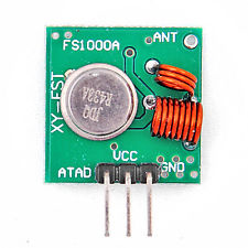
433Mhz Wireless Transmitter Module:
Schematic:
Outdoor Unit1 With LM35 Temperature Sensor
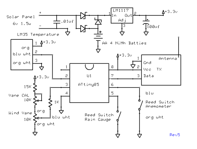
U1 Pin2 = A3 Analog Input…
Outdoor Unit2 With DHT11 Humidity / Temperature Sensor
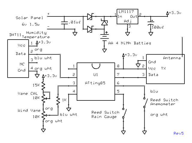
U1 Pin2 = D3 Input/Output…
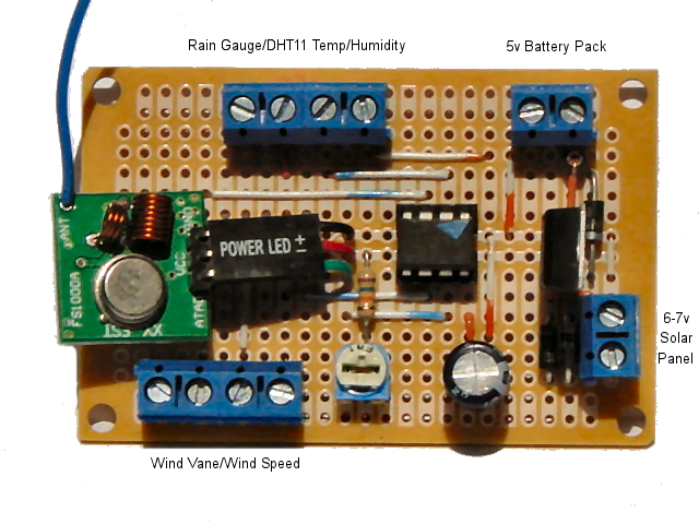
Prototype:
Notes:
| ATtiny85 Power Consumption | |
| ——————————- | 1Mhz BOD disabled |
| 5.5v | 2.67mA |
| 3.3v | 1.05mA |
| ——————————- | 8Mhz BOD disabled |
| 5.5v | 8.94mA |
| 3.3v | 4.20mA |
| ——————————- | 8Mhz BOD disabled – Programed |
| 5.5v | 9.00mA |
| 3.3v | 4.44mA |
| ——————————- | 16Mhz internal BOD enabled |
| 5.5v | 17mA |
| 3.3v | 8.1mA |
| LM1117 | Quiescent Current |
| 5.5v | 5.78mA |
Mar 13, 2014: A lot of updates today Software and Hardware. Hardware reworked the Wind vane circuit installed a Vane CAL potentiometer to calibrate the wind vane.
Steps to calibrate the Wind vane:
- Find the Wind vane potentiometer dead spot that’s (N) North 0 degrees
- Rotate the Wind vane 180 degrees (S) South adjust the Vane CAL potentiometer for 180 degree (S)
- Rotate the Wind vane to (E) East should read 90 degrees and then
West should read 270 degrees.
That’s it for the Wind vane calibration.
Notes: The above Vane CAL update tested with 3.3v Vcc with 1.1v (INTERNAL1V1) Ref, not been tested with 2.56v (INTERNAL2V56) Ref. The 15k resistor / 10k potentiometer not needed with 3.3v Vcc and Vcc (Default) Ref .
Required Libraries:
- #include <TinyDebugSerial> (only for debugging “TX out pin changed to D2”)
- #include <PinChangeInterrupt.h>
- #include <VirtualWire.h>
- #include <TinyDHT.h> (Only For Outdoor Unit2)
Required Function:
- readVcc()
Part List:
- One(1) ATtiny85
- One(1) 433Mhz Transmitter Module
- One(1) LM1117 3.3v LDO Voltage Regulator
- One(1) LM35 Temperature Sensor (Outdoor Unit1)
- One(1) DHT11 Humidity / Temperature Sensor (Outdoor Unit2)
- One(1) .o1 uf Capacitor
- One(1) 100 uf 16v Electrolytic Capacitor
- One(1) 1K Resistor
- One(1) 10K Resistor
- One(1) 10K Miniature Trimmer Potentiometer
- One(1) 10K 360 Degree NO Stop Precession Potentiometer (for Wind vane)
- One(1) 15K Resistor
- One(1) 8pin IC Socket
- One(1) General Purpose PC Board
- One(1) 6v 1.5w Solar Panel
- Two(2) Miniature Reed Switch (for Anemometer / Rain gauge)
- Three(3) 1N8517 Schlocky Diode
- Four(4) AA 1800Mah NiMh Batteries
- Six(6) PC Board Terminals
Dec 10, 2019: Updated the Communication link of the ATtiny Based Wireless Weather Station to ESP8266 WiFi Serial Transceiver. Now have direct access to the weather data through a browser via a WiFi connection.

Anemometer / Windvane made from PVC pipe – fittings
 (See Reference Links: 1)
ESP8266 WiFi Serial Transceiver…


Common abbreviations – symbols – prefixes
- nickel-metal hydride ( cell ) – NiMH
- nickel-cadmium battery ( cells ) – NiCd
- 9 volts battery – 9V – 9 V
- milliampere hour – milliamp hour – mAh – mAhr – mAhrs
- milliampere – mA ( 1/1000 of ampere | 1 A = 1000 mA )
- ampere – A ( electric charge amount measure )
- battery current or capacity – C
- hour – h – hr
- hours – hrs
Current = 81.3 mA
Charger = 6V open 9.95V
Battery = 4.8V Ni-MH 2100 mAh open 5.86V
resistor = (9.95V- 5.86V) / 0.008 A
resistor = 511 ohm charge rate = 4.0 mA
resistor = 1k charge rate = 2.4 mA
Note: 2100 mAh NiMH size AA – 69.3 mA max. current for continuous-trickle charging.
Board Layout & Pin-Out are the same…
                                       Anemometer    Wnd Vane
                                         ano gnd     /\/\/\/\
                                                    gnd cnt vcc
                                          ano  gnd  cnt  vcc
                                          ---  ---  ---  ---
    +| Solar Power 7v
    -|

        Battery 4.8v
           +   -                  gnd  data 3.3v rain
          --- ---                 ---  ---  ---  ---
                             3.3v data nc gnd
                               1    2   3  4   gnd - rain
                                   DHT11       Rain Gauge
Required Libraries:
dht11.h
TimerOne.h
PinChangeInterrupt.h
TinyDebugSerial.h
Reference Links:
1. ESP8266 weather station using Arduino IDE
2. N8MDP Weather Station Anemometer / Wind Vane
3. How to Hookup Davis Anemometer to Arduino (Part 1 of 3)
4. Arduino Rain Gauge Calibration

